
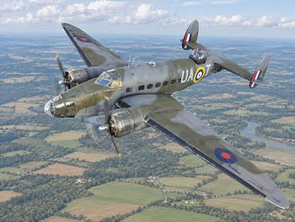
I was assigned by the powers that be at Metro Hobbies to construct one of the new ICM Hudson kits OOB for display in the shop and for me to review the kit – so here it is.
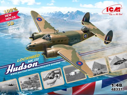
The kit comes with a bunch of sprues/trees and there’s all the relevant pre-building information here:
https://icm.com.ua/aviation/lockheed-hudson-mk-iii/
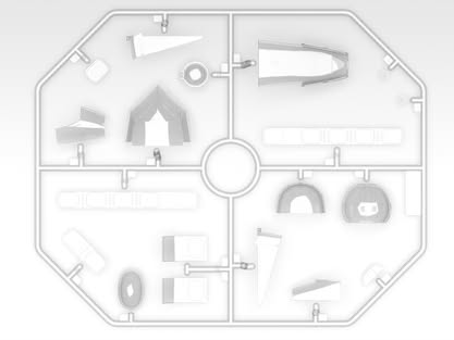
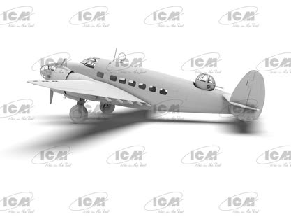

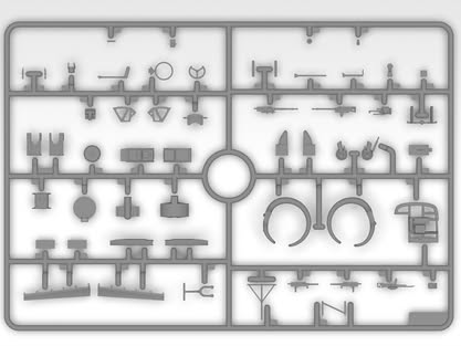
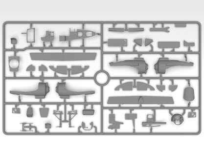
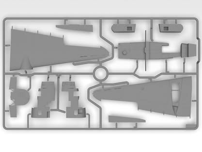
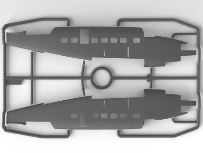
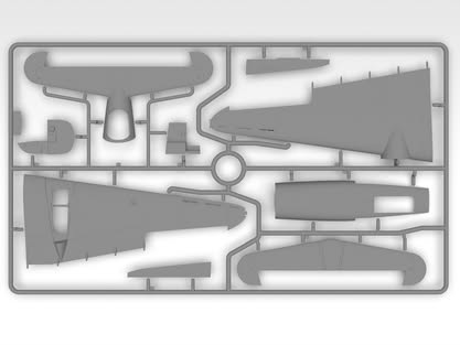
Now this kit presents in the high quality standard we’ve come to expect from ICM but it seriously does have the feeling it was rushed out at the end – I’ll explain as we go.
One really nice addition is the IP decal
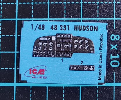
When I came to apply it the fit was… wanting. So when you come to build this kit I suggest applying the decal to the panel before assembly.
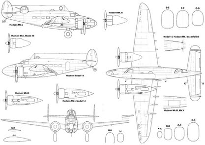
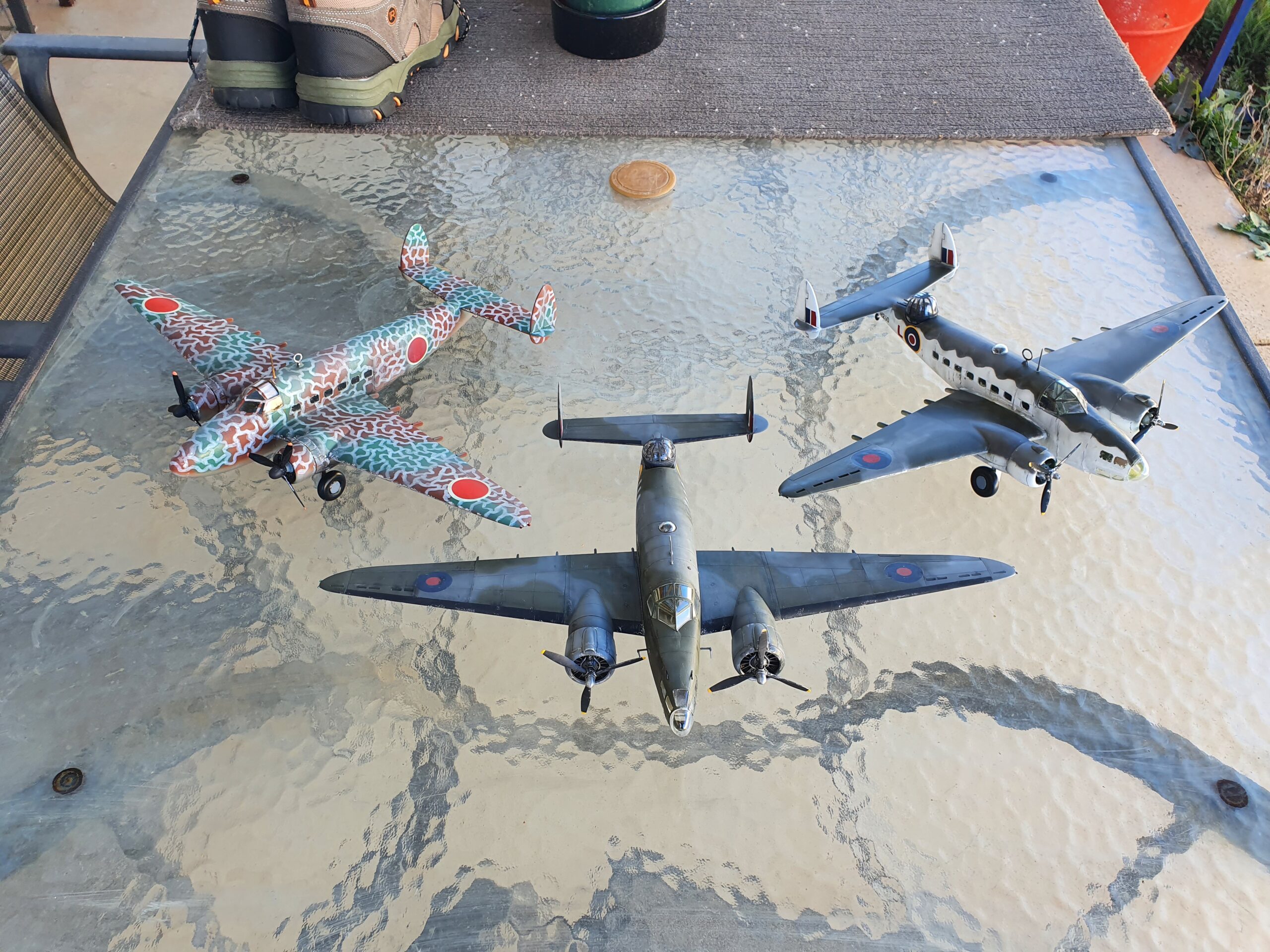
I built this ICM kit in the company of a couple of Classic Airframes kits just to compare.
** News Flash ** No comparison. Dimensions check out but the kits are chalk and cheese – the ICM kit is a quantum leap in engineering and structure – but it does have some shortfalls.
The plastic is very soft and susceptible to melting at the merest sniff of solvent ( glue / MEK ) and if you use a sonic blade like I did on a couple of teensy parts be sure not to loiter lest you liquify the plastic.
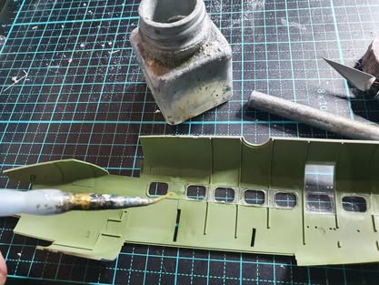
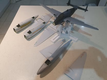
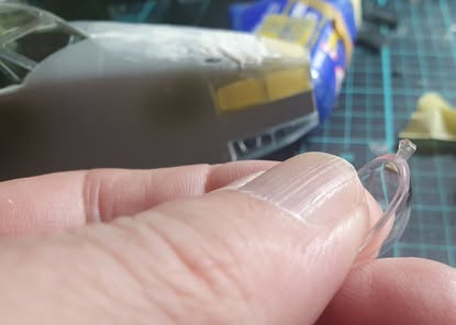
Attaching the windows is easy enough as they’re provided as plates, but make sure you trim them carefully as there is flash. This is where the “rushed” feeling starts to become apparent.
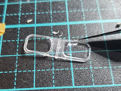
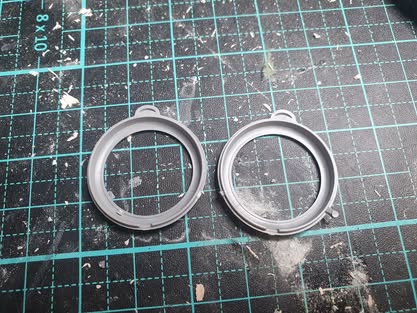
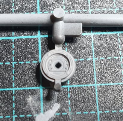
The sprue gates unfortunately override the bevels on many parts. If you look closely at the above pics you’ll see what I mean. The hub in the last pic is typical of what I found, see where the runner meets the part ? It has to be carefully trimmed on two planes to retain the groove required for it to fit in the wheel. This is the same for windows, nacelles, and a few other parts.
So don’t go just cutting parts off the runner without checking.
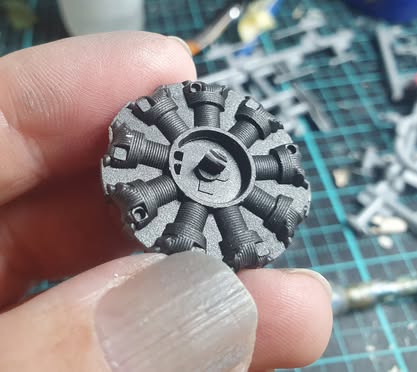
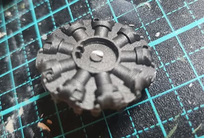
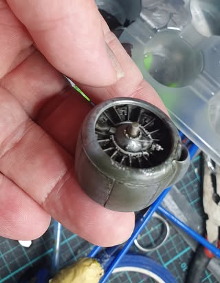
See that ejector pin mark in the middle of the engine ? Try removing it without damaging the surrounding lip.
Left show the mark uncut, the right shows mark cut. The engine won’t fit if this is left intact.
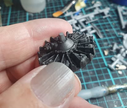
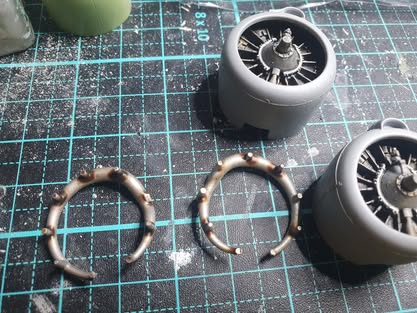
So with a little care the engine parts go together. Any runner detritus, flash or ejector pin marks WILL cause the parts to not sit together.
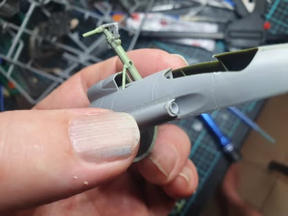
Take a close look at the exhaust – the sprue joining point is RIGHT ON THE EDGE of the thinnest part. Being super soft plastic means if you twist this bit you’ll screw up the exhaust.
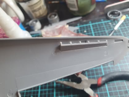
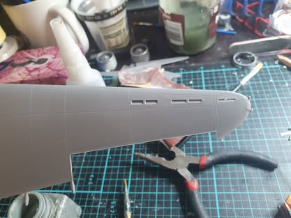
The inside parts of the wing aren’t readily easy to interpret from the instructions – but take you time and trim the excess off – otherwise nothing will sit flush. Also the interior of the wings have ejector pin marks that will need removal.
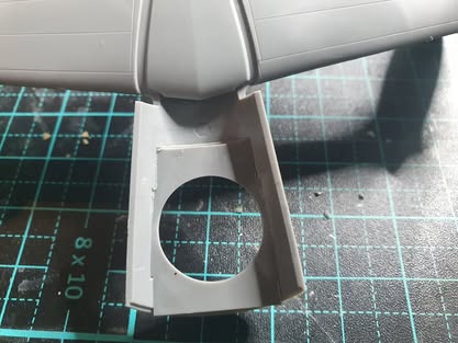
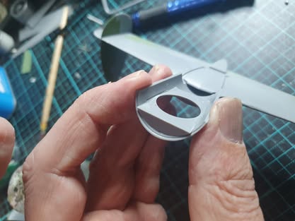
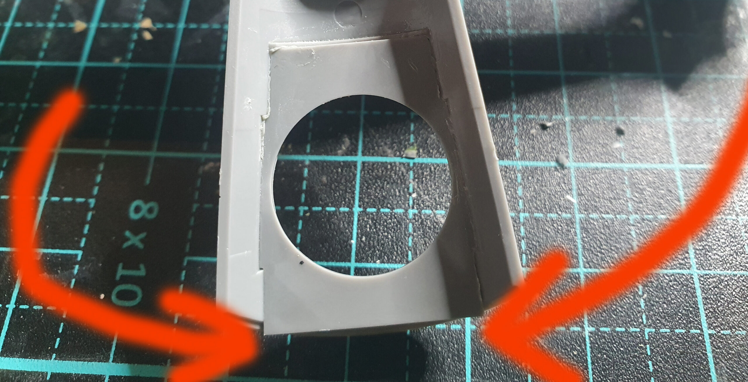
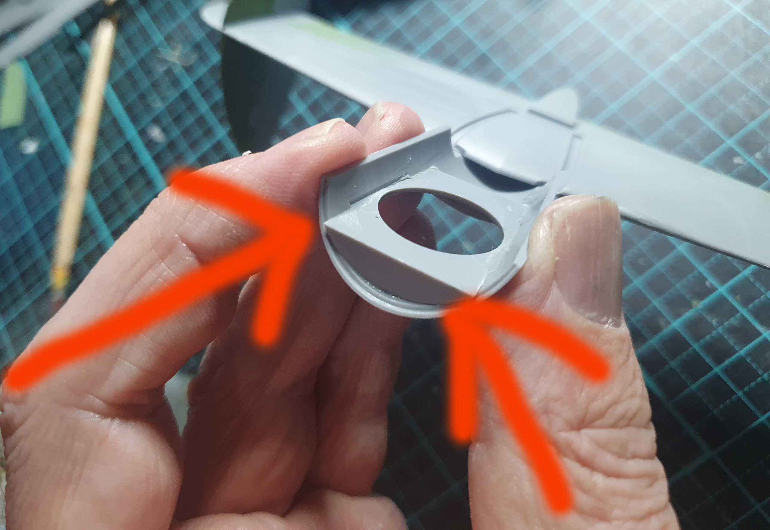
Now this bit actually annoyed me and I had to remake the assembly. This is the tail section incorporating the turret base. The arrows show where the parts erroneously overlapped as the bevels didn’t match the tags – fixed by a little trim so nothing a modeller can’t handle but it really made th kit feel like it had been designed by a committee. See my post on the ICM B26 I converted and the fit in that kit felt nothing like this one.
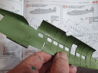
The astrodome requires being attached from the inside which, once you’ve glued it to one side will find it just doesn’t want to line up on always one axis. So I got around it by assembling the fuselage and before attaching the tail inserted it in place ala “ship in a bottle” with the fuselage held upside down and pressured into place with the middle finger. It tends to be a tight fit and I adhered mine in place by painting the periphery with MEK from a fine brush. Left overnight to solidify I then masked it.
More things to be aware of:
The front end of the fuselage has inner walls that slot into place – I caution you that everything has to be dry-fitted/checked etc as if there’s the slightest whiff of misalignment the error cascades.
I think I must have had just such an anomaly as the fuselage didn’t quite fit properly – if I had a second kit I could double check my previous work and see if it was me or the design of the kit
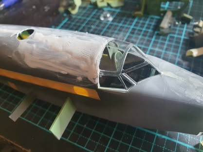
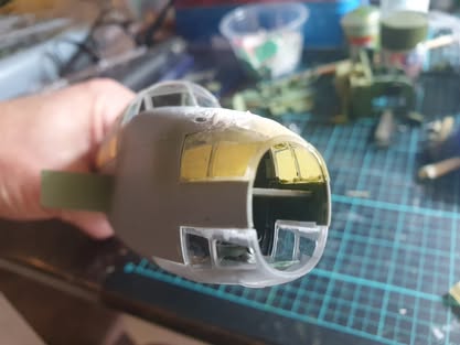
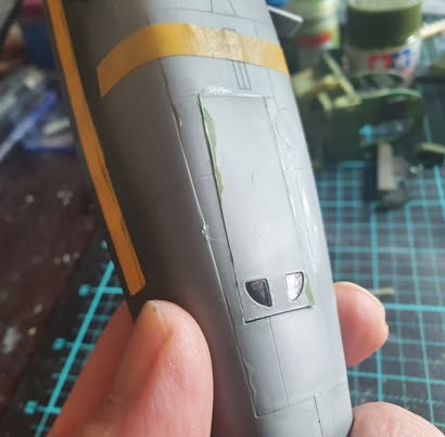
This fit resulted in more filler to be used and some careful sanding afterwards.
Note the front glazing – suffers again from the way they moulded it
The ventral turret opening will be fine if you model it open, but if you do it closed like I did you’ll find the internals bunch up and a step between the door and the floor eventuates.
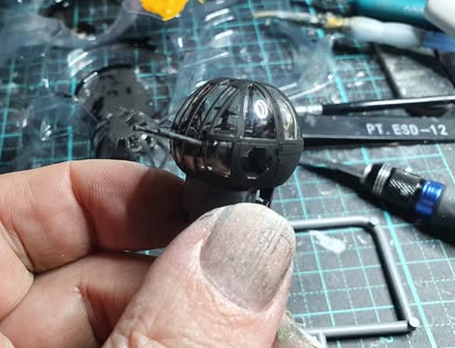
The turret – again, trimming accurately is absolutely mandatory – I ended up with a gap which was my fault as I didn’t dry fit front to back. ( I fixed it with some disassembly, trimming and extreme violence. )
The engine comes in a number of parts and is detailed sufficiently. Looks OK I reckon,
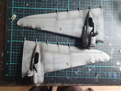
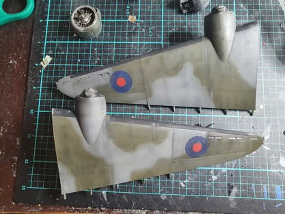
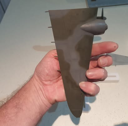
I assembled and painted the wings separately ( used German Field Grey and Basalt Grey as per ICM’s suggestions ) and then came the next minor annoyance.
Compare the next two photos:
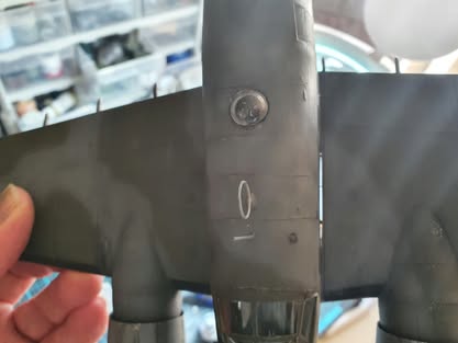
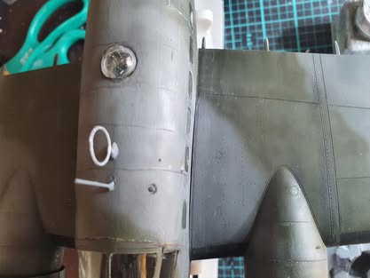
Aside from the fractured DF loop ( that’s how it was on the runner ) note the gap in the wing root where you can see light – the wing root doesn’t fit tightly. The guide rails mean the dihedral is fine and the adhesion is great ( waaaay better than Classic Airframes effort ) BUT, something need to be done to fill the gap. I stuck the wings on and then used a mixture of black acrylic paint and PVA glue painted into the gap and wiped clear with water creating an opaque join that worked a treat with no loss of detail to the wingroot rivetting.
( The DF loop got realigned and glued with MEK )
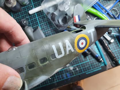
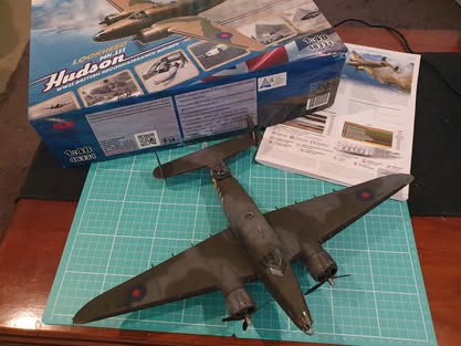
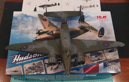
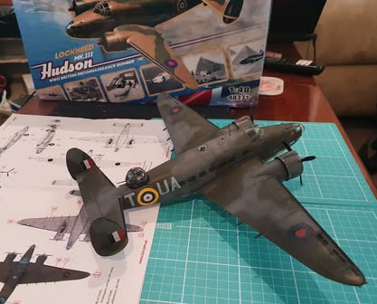
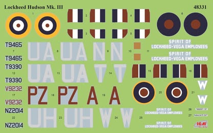
Painting was very basic following the guide as closely as possible and the decals went on without a problem.
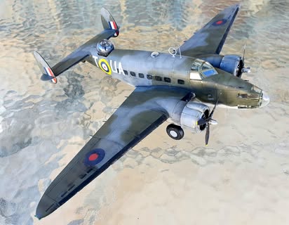
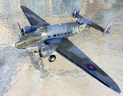
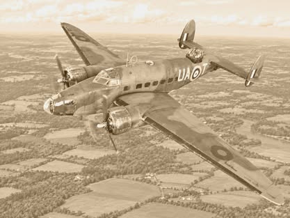
The model is now on display at Metro Hobbies and thanks to them for letting me loose on this.
If you want a 1/48 Hudson this is your kit – hopefully different versions come out so we can do a RAAF one from the box.